|
|
|
|
Seislet transform and seislet frame |
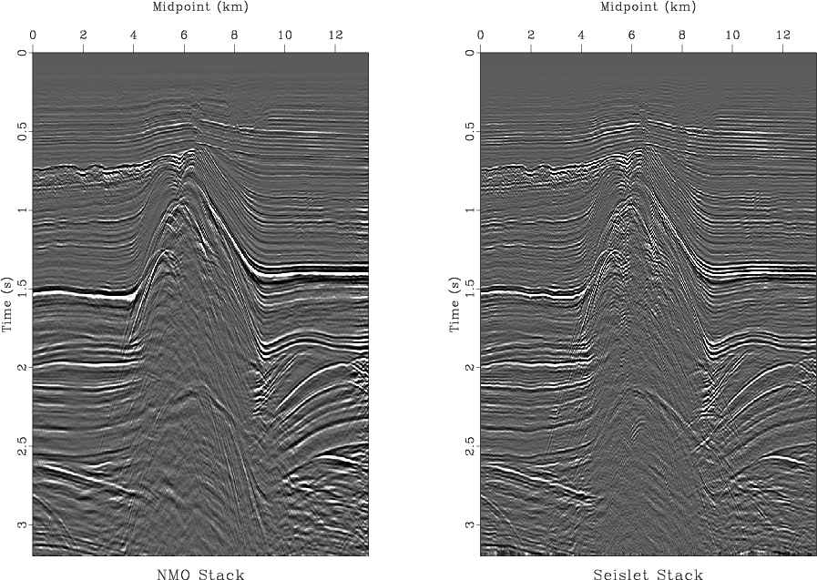
The seislet transform acquires a special meaning when applied in the offset direction on common midpoint or common image point gathers. According to the lifting construction, the zero-order seislet coefficient is nothing more than seismic stack computed in a recursive manner by successive partial stacking of neighboring traces. As a consequence, seislet stack avoids the problem of ``NMO stretch'' associated with usual stacking (Haldorsen and Farmer, 1989) as well as the problem of nonhyperbolic moveouts Fomel and Grechka (2001). All other gather attributes including multiple reflections and amplitude variation with offset appear in the higher order seislet coefficients. Figure 11 shows a comparison between the conventional normal moveout stack and the seislet stack. The higher resolution of the seislet stack is clearly visible. Figure 12 compares the common-midpoint gather after conventional normal moveout correction and an effective seislet moveout computed by separating contributions from individual traces to the seislet stack.

|
|---|
|
sstack
Figure 11. Left: conventional normal-moveout stack. Right: seislet stack. |
|
|


|
|---|
|
nmo,snmo
Figure 12. Input gather after normal moveout correction (a) and effective seislet moveout (b). |
|
|
|
|
|
|
Seislet transform and seislet frame |